by Ron K. Lussier
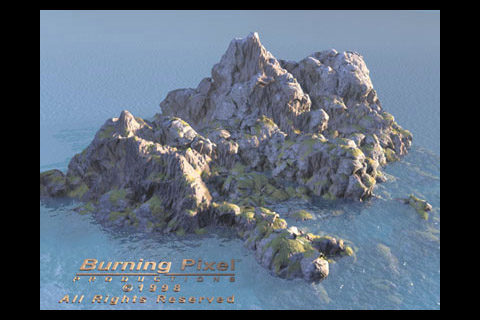
Image © 1998 Burning Pixel Productions - All Right Reserved
This tutorial is an explanation of the first part of some of the basic processes I have used to create 3D landscape files with 3D Studio Max 2+. It creates a mesh similar to the one in the image at the bottom of this file. Possible further additions to the Burning Pixel training materials may go into more detail on the procedures involved in creating and using 3D landscapes.
|
|
1. Start with a Plane... - Create a Plane The Density: setting multiplies the segment count of the grid mesh when rendering. This greatly improves the definition of the landscape without slowing down the user interface, but it can take much more time to build in the "Preparing Objects..." phase of rendering.
|
|
2a. (optional step) Add some initial Bitmap-based displacement for general height control. (Placing "mountains" and "valleys" where you want them.) - Add a Displace modifier to the stack.
|
|
|
2b. Adding procedural displacement to get detailed surfaces... - Add a second Displacement modifier to the stack. (Next, in Step 3 we'll add sub-maps to the Mix map, to actually get some displacement happening.)
|
|
|
|
3. Add displacement Noise maps... In Mat. Editor name the Mix map (from the Displace modifier) "DisplaceMaps". In the Color #1 slot add a Noise map, name it "Small" and change the Size to about 160. Set Type to Fractal and Levels = 6.0 - we need some small detail on the terrain surface so it doesn't look too smooth. Be careful turning the Levels up like this though, it slows down calculations. Above 6 or 7 levels is not often necessary, as there is not usually a visible improvement (depending on the scale of the Noise function). Go back up to the Mix map and add a Noise map to the Color#2 map slot, go into it, name it "Large" and Swap the 2 color swatches. Change the Size to ~600. (I also set Noise Threshold: Low: 0.4 - to smooth the lower elevations, and Phase: 2.0) Click on the Mask slot and Choose Noise, name it "Medium", size to ~300 (I also set Type: Fractal, Levels: 2.0, Phase 4.0).
|
|
4. Adding altitude mapping for strata... - Add a UVW modifier to the stack.
You can use the Mapping: Box setting to visually check the height of the mapping coordinates in the viewport, but be sure to change back to Planar! If you make major changes to the height of the terrain you will need to update the Height value here to cover the taller mesh. |
|
|
|
5. Create a simple height based material. - Assign a Standard material to the terrain object. Click on the Diffuse channel's map slot and pick Gradient. To orient the map to the "altitude mapping" coordinates we've applied switch to WU and enter 90 in the Angle:, W: field. For this example, the top will be snow-like (maybe mineral deposits), so leave Color#1 as white, make Color#2 a dark muted brown or gray and Color#3 a "sandy" tan color. (Gradient) Noise Settings: Amount: ~0.5, type: Fractal, Size: ~0.5
|
|
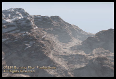
6. Tweaking the settings... Try adding some "Grain" to the middle dirt/rock color and to the Sand by adding small scale Noise functions to color slots 2 and 3. In the DisplaceMap's "Large" Noise map, try turning up the Low: Noise Threshold (as mentioned above). This will give you more prominent, and smoother, low areas in the landscape. Add another small scale Noise in the Terrain material's Bump map slot to help break up the surface more. This helps the final image quite a bit. (Size ~5 or less... depends on how close the camera is to the surface.) Try changing various settings in the displacement maps. Changing the Phase of the Noise maps can result in drastically different landscapes. With some tweaking, a little atmosphere and lighting, you can end up with something like this... |
|
This tutorial is © Copyright 2000 Ron Lussier
All Rights Reserved - Do not re-distribute or reproduce.
3ds MAX is a registered trademark of Autodesk, Inc.
| Home
| Info
| 3ds Max
| Music
| Photography
| Vector Graphics
| Dancing Baby
|
| Graphics Gallery
| 3D Stereo Gallery
| Brazil Gallery
| QuotesBlog
|
![]()